
Hybrid Testbed Guitar
| 08/06/2025 | Written By: Kim Ippolito | Formatted/Edited By: Lauren Ippolito |
I was interested in making a testbed guitar to use to investigate different acoustic properties of the guitar, to experiment with different electronics, and characterize different pickup configurations. At the time, I wasn’t sure of the direction of my investigations, but I knew I was interested in investigating both acoustic and electric guitars. Thus, I was inspired to create the testbed guitar in the format of a hybrid guitar.
Thus, I wanted to create a testbed guitar that has:
- Two microphones (one in soundhole and one embedded internally away from direct feedback)
- Thin hollow body with circular soundhole
- 25.5 inch scale length
- Tummy cutout and forearm contour
- Removable front soundboard for access to sound cavity and removable back control panel for
access to controls cavity - so that I can have easy access to internal electronics
- Three magnetic pickups
- Three piezo pickups
- Active electronics to send each individual pickup to an external audio interface, or
directly to an amplifier via a 5-way switch (similar to Stratocaster wiring)
Planning and Design
Body Design
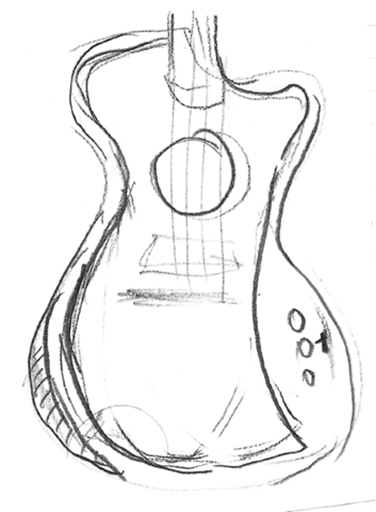
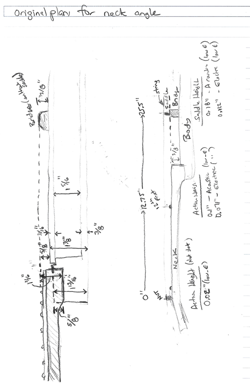
To get it started, I created the following sketch of what I wanted, and a rough template of the body shape – including control cavity, tummy cutout, forearm contour, etc.
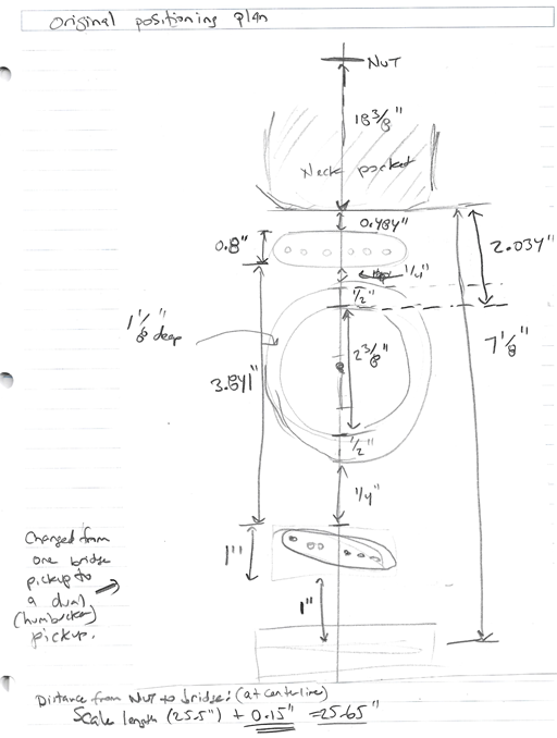
Then I create detailed diagrams of the positioning of all components on the body.
Electronics Design
Then, with the physical design in place, I created a plan for the electronics, as shown below. There are eight recording devices (3 magnetic pickups, 3 piezo pickups, and 2 microphones) and two output options – a 9-pin connector to connect the 8 outputs (plus ground) to an audio interface, and a standard guitar output jack to connect to an amp. The microphones will only be accessible via the 9-pin cable, while the piezo and magnetic pickups can be sent to either output (via a switch for the piezos and a switch for the magnetic pickups).
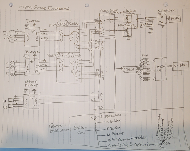
The knobs on the guitar (magnetic pickups volume control, piezo pickup volume control, and tone control) are only relevant for the output jack, and not the 9-pin connector.
This design requires a 9V battery to be in place for both outputs (the 9-pin output and the standard output jack). Alternatively, to avoid the 9V battery when using the output jack, I could have limited the piezos to only go to the 9-pin output. However, I wanted to be able to test and use the piezos without an external computer, thus I accepted the requirement of a 9V battery.
This design puts the active electronics inside the guitar, rather than outside in a separate component, in order to minimize noise.
Buffer
The buffer was designed to work with 9V power, fit on a 20x14 Perf Board, and support three independent pickup devices (Magnetic or Piezo). Thus, the hybrid guitar will require two boards – one for the 3 Magnetic pickups, and the other for the 3 Piezo pickups.
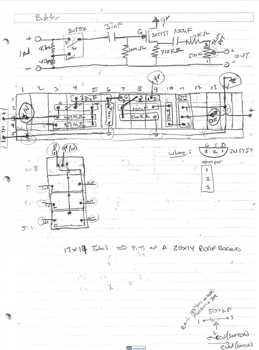
(Note: When fabricating the boards, I updated the board design to include the power conditioner and LED indicator circuit that is shown in the next section for the microphone preamp.)
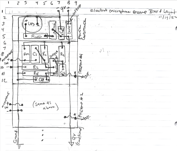
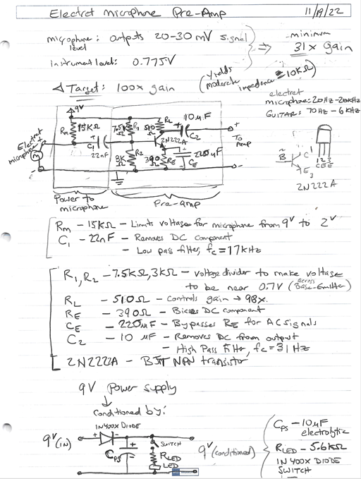
Microphone Pre-Amp
The following preamp design was selected, where two pre-amps were fit on a single board.
Additional Design Decisions
- 27 mm piezo pickups
- A500K potentiometers for volume
- B500K potentiometers for tone
- 0.047 uF capacitor for tone
Build
Body
To create the body, I glued a numerous boards of wood together to make a block of wood with a thickness slightly larger than 1 7/8” and slightly larger than the dimensions of the template. Then, I followed the rough template to create the body shape that I desired, including the soft rounded edges, “tummy cutout” and “forearm contour”. This included sanding it numerous times with different grit sandpaper until it was the smoothness desired.
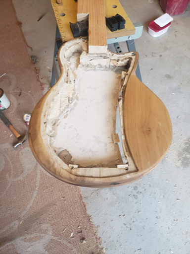
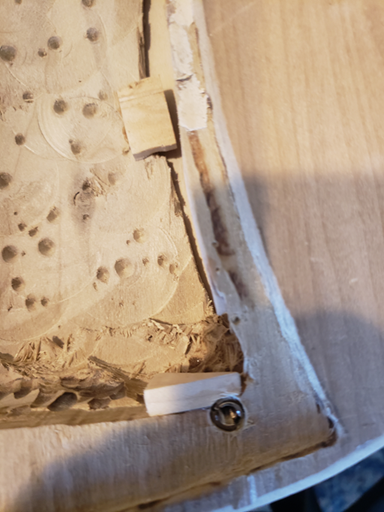
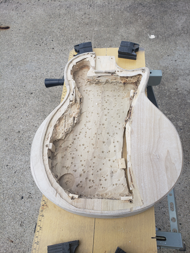
Once complete, I drilled out the neck pocket, and hollowed out the body from the front (for the sound cavity) and back (for the controls cavity). I tried to keep the remaining thickness at 3/16”. And I created a lip for the soundboard and controls cover 3/16” deep and at least 1/4” wide.
Soundboard and Magnetic Pickups
Then, I created a 3/16” thick soundboard and controls cover using an available tonewood. And I added bolts in the body to allow the soundboard and controls cover to be easily removable, yet have a strong connection to the body
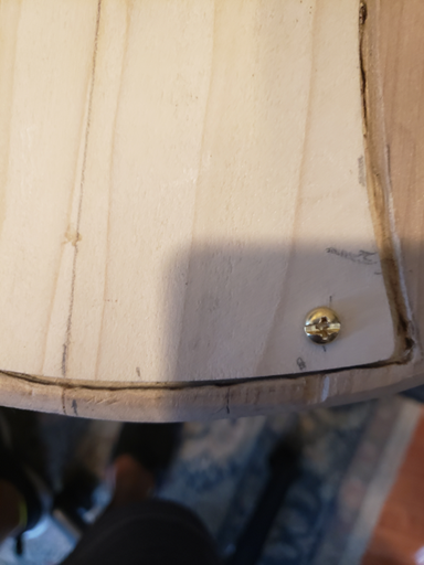
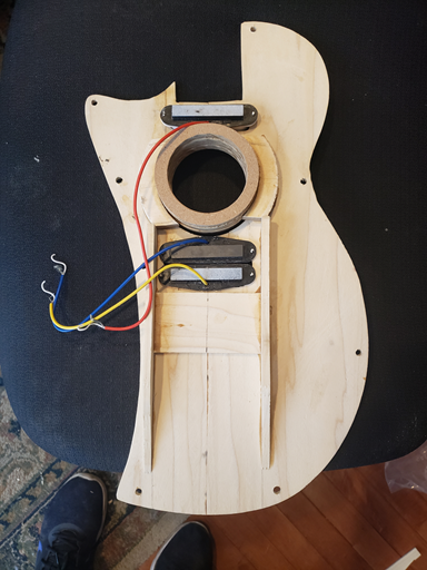
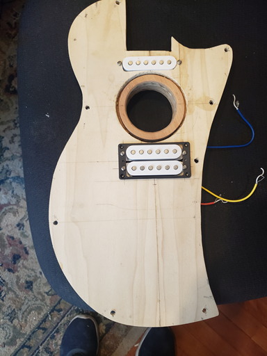
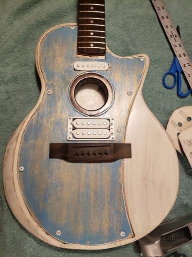
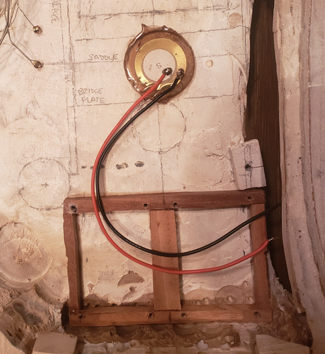
Then, in the detachable soundboard, I created the soundhole, added bracing (to support the force of strings pulling on the bridge), added a bridge plate (to add support to the bridge that will be attached later), and cut out the holes for the three magnetic pickups. Note that the central soundhole limited the location of the middle pickup, so I organized two of the pickups together in a humbucker format (i.e., rotating one of the pickups 180 degrees). I plan on eventually putting several soundholes that can be plugged so that I can study the effect of soundhole placement and sizing. (I didn’t do this initially, since I was not certain how the additional plugs will impact the soundboard’s tone.)
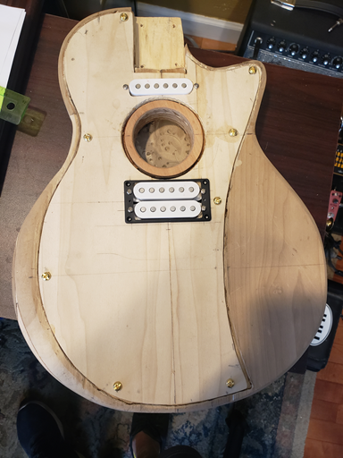
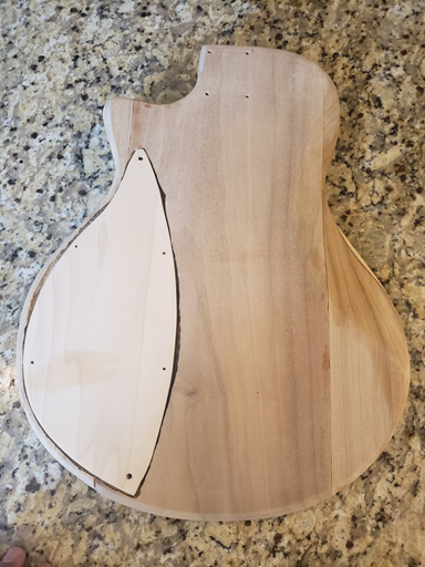
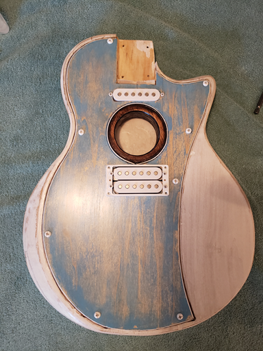
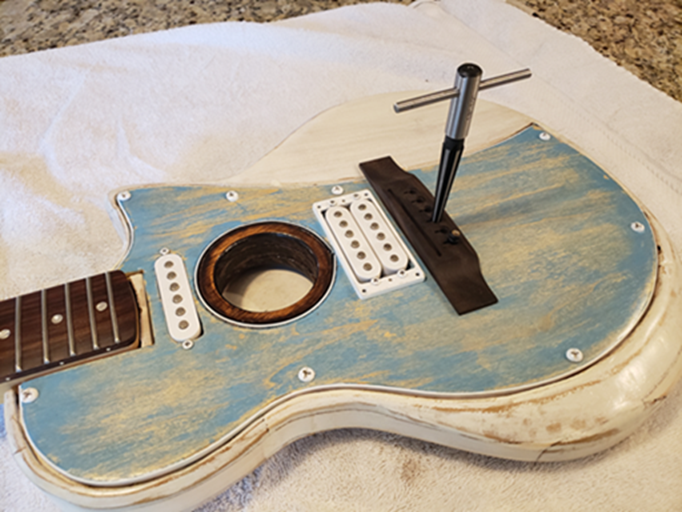
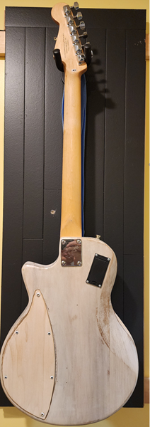
The fitted soundboard on the body, and the control panel cover are shown below.
Neck
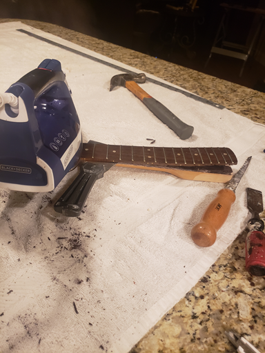
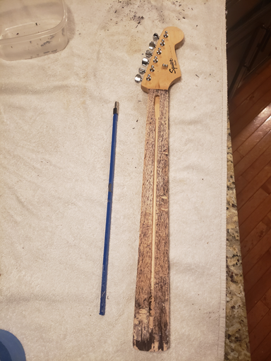
Fortunately, I had an extra guitar neck from a Squier Stratocaster. The neck had a damaged truss rod, so I had to replace it before attaching to the body.
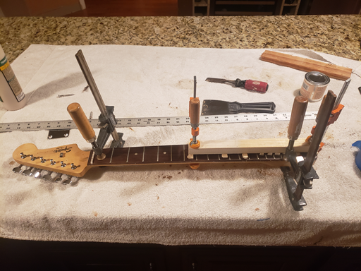
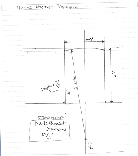
Then, I was able to connect the neck to the body, and adjust the neck pocket so that the neck angle was per the plan.
Paint
I added a white binding around detachable soundboard to give it a nicer look when installed.
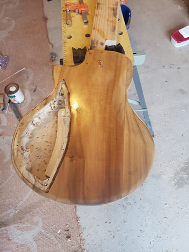
Then, I stained the soundboard blue and the body white, and added a rub-on polyurethane top coat.
Bridge
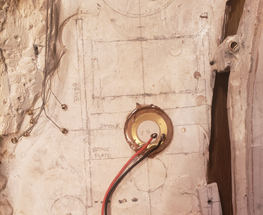
Now that body is painted, I attached the bridge and drilled holes for the strings. Note that there is a bridge plate on the back side of the soundboard under the bridge, to give it better support when the installed strings are under tension.
Under the bridge, I installed a grounding plate to touch all of the installed strings. On the grounding plate, I soldered a ground wire which will (later) connect to a common ground.
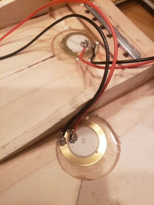
Piezo Pickups
I installed the three piezos such that:
- Piezo #1 is on back of soundboard, as close to bridge directly below bridge.
- Piezo #2 is also on soundboard, but adjacent to vertical brace (which dampens the vertical waves measured by Piezo #2).
- Piezo #3 is on back, directly underneath bridge.
They were installed by cutting a hole for the piezo disks to fit into, placing the piezo disk as deep in the hole as it will go, and then adding to hole to hold piezo disk in place.
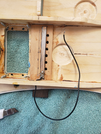
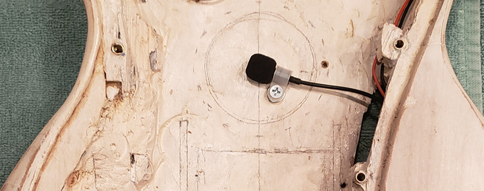
Microphones
The two microphones were then installed – one inside the soundhole, and the other tucked inside the guitar hollow body, at bottom furthest point from the soundhole.
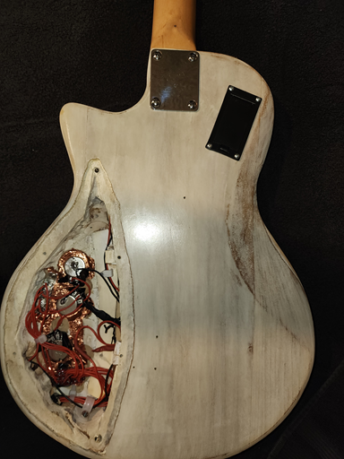
Body Modifications for Electronics
Next, I cut a hole and installed the battery compartment in the top left back of guitar body. And I cut out the holes for the three pot knobs, a 5-way switch, two switches, and the two output ports (9-pin connector and standard guitar output jack connector). To get a good fit for the pot knobs, I reduced the thickness in the area of the controls to around 1/8”.
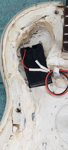
Then, once all the holes were cut and I tested that all components fit properly, I then installed copper tape into control cavity prior to installing the electronic components, so that they can easily share the same ground. (Also, as you can see in above picture, I added guitar strap locks.)
Then I added a platform inside the guitar hollow body for the active electronics to reside.
Electronics
The three electronic boards (2 buffer boards, 1 microphone pre-amp board) were created, per the design described earlier.
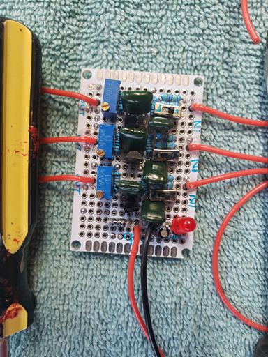
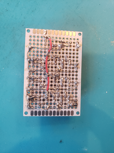
These boards were installed onto the platform inside body of the guitar. All components were connected by wire, and soldered, per the design.
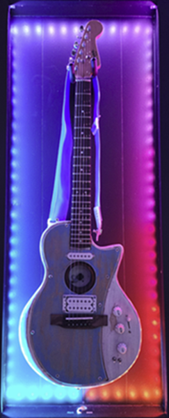
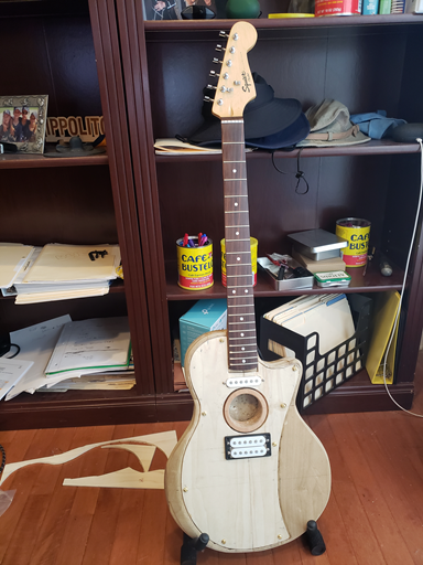
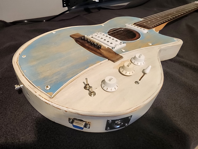
Completed Project
Now, with the flip of a switch, I can either play the piezo and magnetic pickups through an amplifier, or I can record all individual pickups and microphones through an 8-channel audio interface.
I can now use this hybrid guitar as a testbed for future investigations and evaluations.